Single Phase Motor Starter Wiring Diagram Database
By Leela Prasad. The primary function of a motor starter is to start and stop the motor to which it is connected. These are specially designed electromechanical switches similar to relays. The main difference between a relay and a starter is that a starter contains overload protection for the motor. So the purpose of the starter is twofold, i.e.

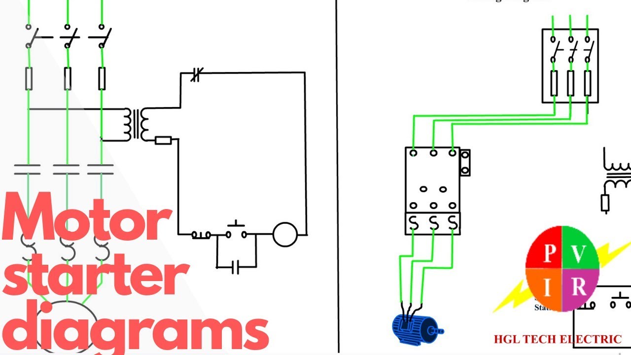
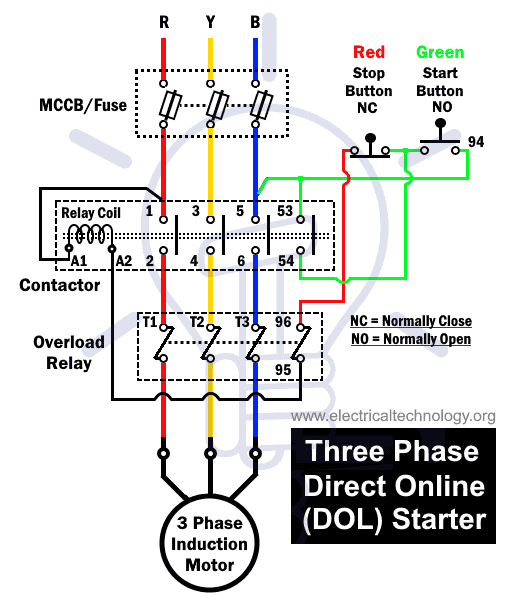
DOL Starter Wiring Diagram For 3 Phase Motor Controlling
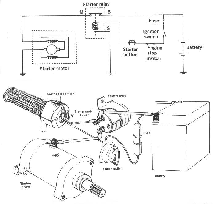
Learn how your vehicle's starter motor and ignition system circuit work, including how the ignition switch, relay and safety gearshift are wired to kick star.

Engine Starter Motor Diagram Wiring Diagram Schemas
A motor starter is an electrical device that is used to start & stop a motor safely. Similar to a relay, the motor starter switches the power ON/OFF & unlike a relay, it also provides a low voltage & overcurrent protection. The main function of a motor starter is; To safely start a motor. To safely stop a motor.

Triaging a nocrank condition and testing a starter motor Hagerty Media
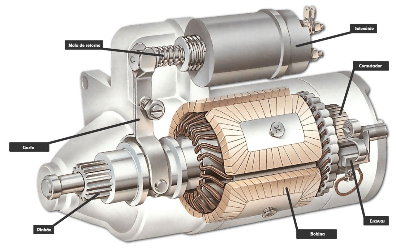
See how the starter motor works inside below. The starter motor is powered by the car's main 12-volt battery. To turn over the engine, the starter motor requires very high electric current, which means the battery has to have sufficient power. If the battery is discharged, the lights in a car might work, but it won't have enough power (current.
Basic PLC program for control of a threephase AC motor
Motor Starter/Control Basics Get the FULL video transcript here: https://www.rspsupply.com/education/a-32-motor-starter-basics/Want to see similar products t.

Start Stop 3 Phase Motor Starter Wiring Electrical Engineering Updates
Definition of Starter Motor. A starter motor or starting motor, or cranking motor, is a direct current motor that cranks the engine for starting. Cranking the engine means rotating the crankshaft by applying torque on it so that the piston may get reciprocating motion.. The starting motor is mounted on the engine flywheel housing. It is a series wound and is made to run at low voltages with.

3 Phase Motor Starter Wiring Diagram Pdf Free Wiring Diagram
Siemens Motor Starter Wiring Diagram (A Complete Guide) by Charles Clark November 7, 2023. Siemens motor starters are essential for controlling the operation of electric motors. They ensure that motors start, stop, and run smoothly, protecting both the equipment and the personnel involved. Understanding how to wire them is crucial for various.
Difference between DOL and Soft Starter for Electric Motors
Wiring Diagrams ww introduction This booklet has been prepared as a guide to some of the useful ways Allen-Bradley's manual and magnetic across-the-line starters. Bulletin 520 Multi-Speed Motor Starters . . . . . . . . . . . . . . . . . . . . 49 thru 51 PLATE PAGE 14 thru 17 18 and 19 20 thru 24 25 26 and 27 28 thru 32 33 and 34 35 thru 37.
Motor Starter Wiring Diagram Pdf Download Wiring Diagram Sample
This video will EXPLAIN how a three wire motor starter circuit works, show wiring diagrams of the circuit in each stage of the process and show examples of t.

DOL Starter (Direct Online Starter) Details Including Workign
Starter Motor. The car's starting system works by converting electrical energy into mechanical energy to make the engine run. A starter motor and solenoid are tightly integrated pairs and the heart of the starting system. It is used to turn on the engine, without it, the engine isn't turning over and the car won't start.
Starter Motor Circuit
An example of a typical, non-computer controlled starter wiring diagram. Now you know how a starter motor works. But what about the rest of the starting system? Starting circuit operation is fairly straightforward. When the driver turns the key to the "start" position in a typical starting system, battery voltage flows from the ignition.

🔴 Forwardreverse motor starter diagram 👥 Save this post. Share and tag
If you don't see what you're looking for, please ask. Springer Controls has a certified UL508A panel shop to build custom starters and control panels up to 500V. For any custom options like HOA (Hand-Off-Auto) starters, pilot lights, control transformers, or volume purchases, please contact us at 888-357-2138.
O motor de arranque parou? Veja o que fazer! InstaCarro
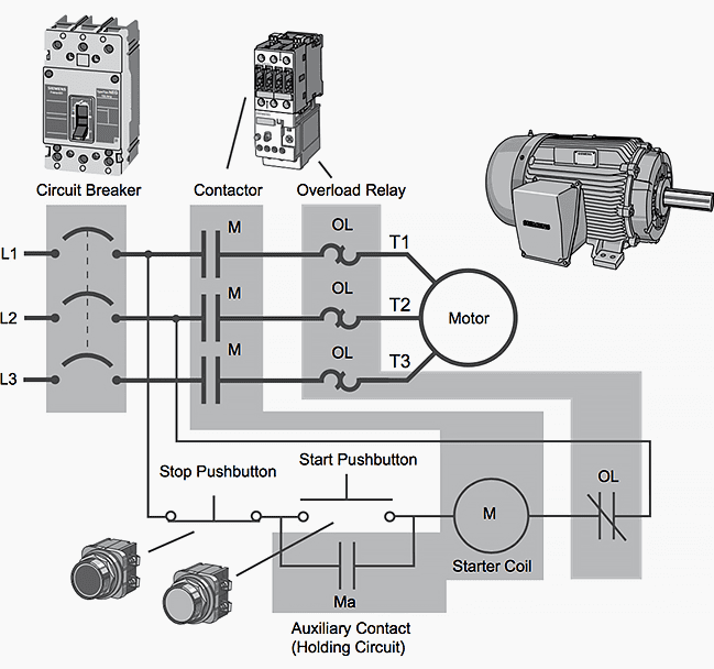
The three-phase electromagnetic motor-starter consists of a power contactor and an overload relay, as shown in Figure 2. The mechanical closing of the power contacts is accomplished by an electromagnetic field, which is produced by a coil of wire contained in the solenoid. The solenoid coil can be activated with an electrical signal from a.
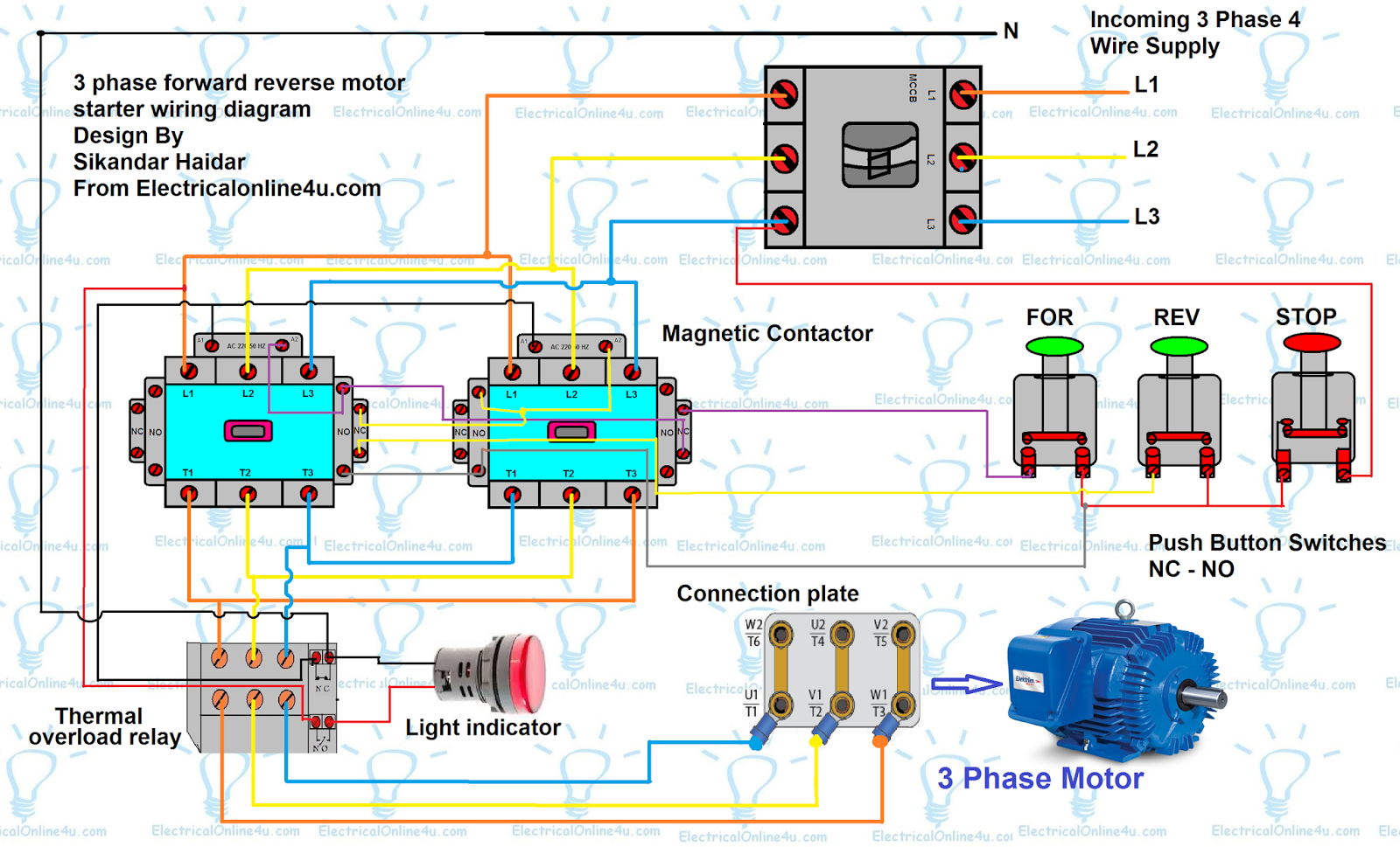
Forward Reverse Motor Control Diagram For 3 Phase Motor Electrical
A motor starter is a combination of devices used to start, run, and stop an AC induction motor based on commands from an operator or a controller. In North America, an induction motor will typically operate at 230V or 460V, 3-phase, 60 Hz and has a control voltage of 115 VAC or 24 VDC. Several other combinations are possible in North America.

Eaton Motor Starter Wiring Diagram Free Wiring Diagram
The motor starter wiring diagram is an essential tool for understanding how a motor starter is wired and operates. It provides a visual representation of the electrical connections and components involved in starting, stopping, and controlling a motor. One key aspect of understanding motor starter wiring diagrams is recognizing the different.

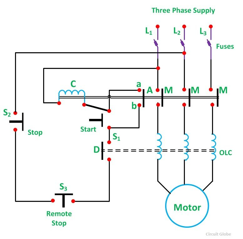
[DIAGRAM] 3 Phase Starter Diagram
The electromagnet that holds the starter in the run position is in the field circuit. This type of starter can be used for shunt and compound motors, and if the field is lost, the starter drops out, protecting the motor against runaway. FIGURE 2: Three-point manual DC motor starter circuit diagram. The disadvantage of this type of starter is.